In the case of boiler room security, we monitor the leakage of gas that is used for heating. Thus, we may encounter requirements for methane or propane-butane detection. In addition, carbon monoxide (CO) may be required to be detected, which can escape in the boiler room due to poor flue gas extraction.
For the design of boiler room security, we can refer to EN 60079-29-2 ed 2. There is no general guide to the number of detectors and their location. It always depends on the specific situation. If we consider the above mentioned standard to determine the number of detectors, we can use one of the following schemes.
Wiring for small boiler rooms
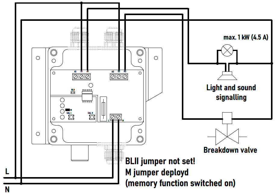
For small boiler rooms where there is a requirement for one or two combustible gas or CO detectors, we can use the GC20P-230V for combustible gas detection or the GICO20P-230V for CO detection. These are 230 V / 50 Hz mains powered detectors with power output relays. The detectors are two-stage. In the GC20P-230V, the first stage switches on when 10% LFL is exceeded and is used for switching on warning alarms or air handling systems. The second stage is switched when 20% LFL is exceeded and can be used to control an emergency valve. Similarly, we can also use the GICO20P-230V, which switches the first stage when 50 ppm CO in the air is exceeded and the second stage when 100 ppm CO in the air is exceeded.
Wiring for larger boiler rooms
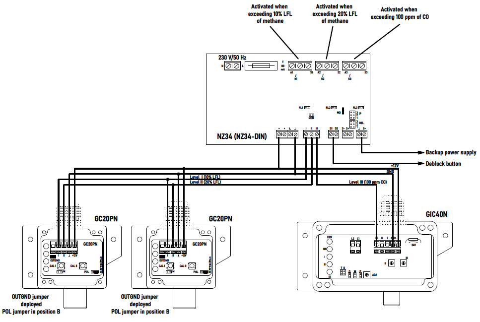
For boiler rooms where more detectors are required, a configuration consisting of a single power supply to which multiple detectors are connected is preferable. Typically a NZ34 power supply and GC20PN or GC20PK or GI30WN or GI30WK detectors can be used to detect combustible gases. If CO detection is required, we can also connect a GIC40N detector to the power supply.
We have several options for connecting the detectors. The main decision criterion is whether protection against theft, power loss or wire drop is required. If this protection is not required, we can use a simpler parallel connection. An example wiring diagram is shown below. We would wire the GI30W detectors in a similar way to the GC20PN.
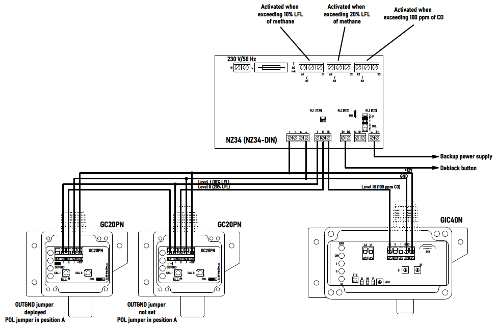
If power loss or wire break protection is required, we can use a circuit using a fault loop for stage II. The solution is similar to the previous case, differing only in the way the wires are connected and the jumper settings.
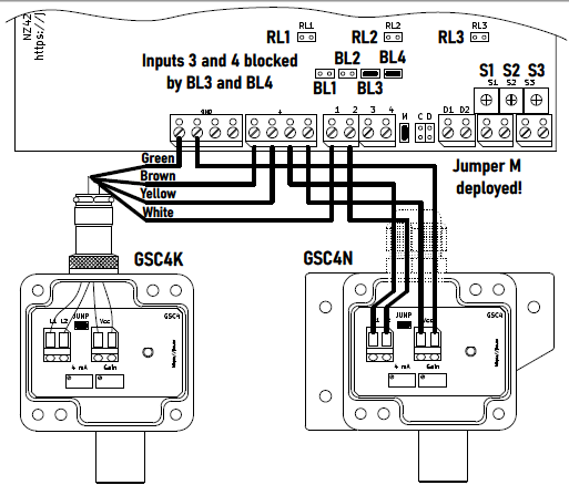
Another option is to use the GSC4N or GSC4K sensors together with the NZ425(-DIN) power supply. These sensors use a 4-20 mA current loop for signal transmission between the sensor and the power supply. This ensures easy detection of a detector fault (power loss, wire break or short). Up to 4 GSC4 sensors can be connected to one NZ425 power supply. By setting the trimmers on the NZ425 source, we can then set up to three levels to which the output relays will respond, or we can use one of the relays to indicate a system fault. CO detection must then be provided separately. For example, using a GIC20P-230V detector, or using a GSU2N CO detection sensor with a 4-20 mA output and an NZ425(-DIN) source.
This text is for information only. For a proper design of the gas detection system it is necessary to study the currently valid regulations and standards and to refer to the technical documentation of the individual types of detectors, sensors and sources. J.T.O. System, s.r.o. assumes no responsibility for the use of this text. If you are unsure, please contact us by e-mail or telephone.